October 10, 2026
Precision Sheet Metal Fabrication Process and Essential Terminology
A Precision Sheet Metal Fabrication Process turns flat metal into a functional enclosure, bracket, panel, frame or equipment component through a controlled sequence of cutting, forming, joining and finishing operations.
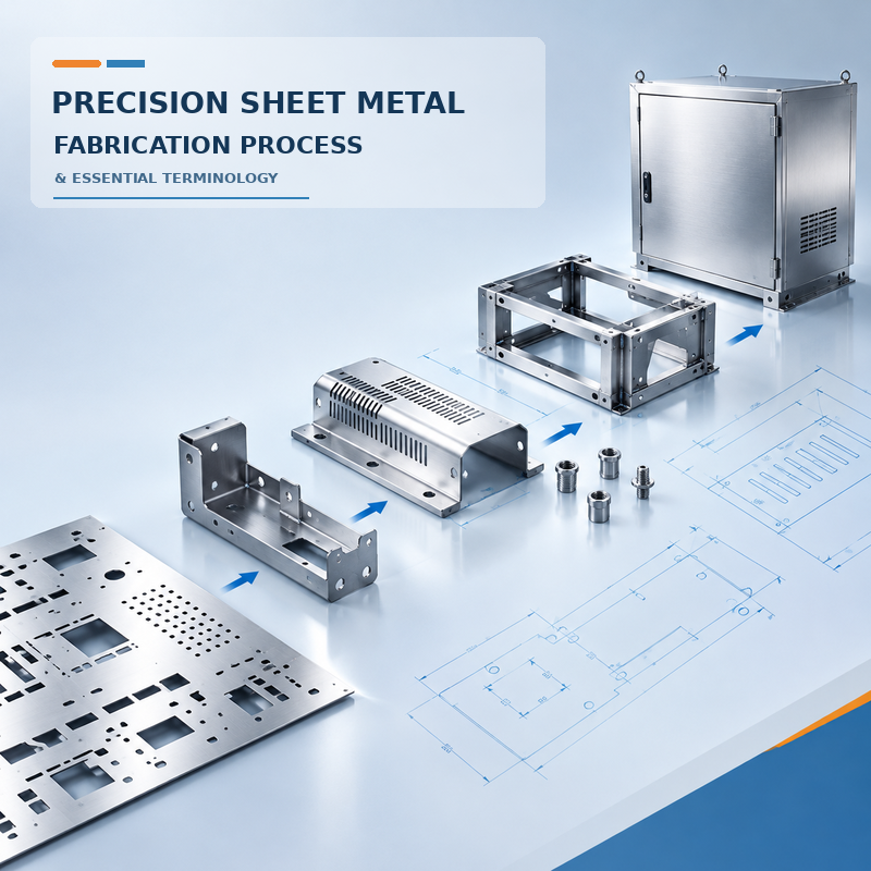
A Precision Sheet Metal Fabrication Process turns flat metal into a functional enclosure, bracket, panel, frame or equipment component through a controlled sequence of cutting, forming, joining and finishing operations. The value of understanding that sequence is practical. Engineers can specify drawings more clearly, buyers can compare quotations on the same basis, and production teams can identify which operation controls dimensional accuracy, appearance or assembly performance.
Hongdingtian Suzhou Intelligent Technology Co., Ltd., operating as HDT Technology, provides sheet metal cutting, CNC press brake bending, welding, surface finishing and mechanical assembly for industrial projects. Our website lists applications in energy equipment, electrical cabinets, automotive parts, laboratory equipment and custom machine structures. Based on the terminology used in daily fabrication, this article explains the major process groups and clarifies expressions that are often translated too broadly in international purchasing documents.
Manufacturing Process and Terminology Map
• Material Preparation Begins With the Final Function
• Blanking and Cutting Establish the Starting Geometry
• Holemaking Includes More Than Punching
• Forming Creates the Three Dimensional Part
• Flanged Holes Embosses and Bridge Features Need Precise Names
• Riveting and Thread Operations Build Assembly Interfaces
• Welding Sequence Controls Geometry as Well as Strength
• Deburring and Surface Preparation Protect the Final Finish
• Filling Heat Shrinking and Corrective Operations Need Boundaries
• Digital Planning Connects the Operations Into One Route
• A Complete RFQ Uses Terms Together With Measurable Requirements
• Buyer Questions About Precision Sheet Metal Terminology
Material Preparation Begins With the Final Function
Before the first cut, the project team reviews material grade, thickness, sheet condition, grain or brushed direction, surface protection and the dimensions that control final assembly. Carbon steel, stainless steel and aluminum respond differently to cutting heat, bend radius, springback, welding and finishing. A correct material callout is therefore part of process planning rather than a purchasing detail that can be resolved after production begins.
The drawing should separate functional interfaces from general geometry. Mounting holes, sealing edges, door openings, hinge locations and mating faces may require tighter control than hidden outer edges. This priority affects how the blank is nested, which features are cut before bending, whether machining is needed after welding and how the part will be measured. A clear datum scheme prevents every operation from creating its own interpretation of the drawing.
Blanking and Cutting Establish the Starting Geometry
Blanking is the first physical stage. In a broad sense, it includes shearing, laser cutting, punching and other methods used to separate a required shape from sheet stock. Shearing produces straight strips or rectangular blanks efficiently. Laser cutting creates complex external profiles and dense hole patterns without a dedicated hard tool. A CNC turret punch uses programmed tooling to make holes, slots, louvers and formed features in a repeatable sequence.
The word blanking also has a narrower stamping meaning. In die cutting, the material separated from the surrounding sheet becomes the required product profile, while in punching the removed slug is normally waste and the remaining sheet or workpiece contains the useful hole. Keeping these meanings clear helps international buyers distinguish a general cutting stage from a dedicated blanking-die operation.
Holemaking Includes More Than Punching
Punching creates locating holes, mounting holes, ventilation openings and other repeat features using a punch and die. Perforating, sometimes described as mesh punching, produces repeated arrays for airflow, acoustic covers or protective screens. The pitch, open-area ratio, edge distance and sheet distortion all need attention because a dense pattern can weaken the panel or cause it to curve after processing.
Drilling is commonly used when a hole requires a different accuracy, diameter or access condition from the original blanking route. Enlarging or reaming an existing hole brings it to the specified diameter or improves the finished condition. A buyer should state whether hole size, location, perpendicularity or thread engagement is the critical result. Simply writing drill after laser does not define the acceptance requirement.
Forming Creates the Three Dimensional Part
Bending uses a press brake and tooling to create an angle through controlled plastic deformation. The finished result depends on material thickness, bend radius, die opening, rolling direction, tool condition and springback compensation. HDT Technology publicly lists CNC press brake bending with CNC angle control and bending lengths up to four metres. Actual part suitability still depends on geometry, tooling access and the required tolerance.
Forming is a broader term that also includes drawing, embossing, flanging and other pressure-based shape changes. A drawn shell, a raised stiffening feature and a flanged hole serve different purposes. The process plan should show whether a feature is made in the turret punch, a dedicated press tool or a secondary hydraulic operation, because tool access and sequence influence nearby bends and holes.
Process group | Common operation | Primary purpose | Buyer control point |
Cutting and blanking | Shearing laser cutting or die blanking | Create the flat profile | Material revision edge condition and datum |
Hole and feature work | Punching perforating drilling and enlarging | Create openings and functional features | Diameter position pitch and distortion |
Forming | Bending flanging embossing and drawing | Create three dimensional geometry | Radius angle springback and tool access |
Joining | Press riveting blind riveting and welding | Build assemblies and threaded interfaces | Fastener identity weld callout and distortion |
Surface preparation | Deburring brushing polishing and pretreatment | Prepare appearance and coating adhesion | Cosmetic direction cleanliness and masking |
Final verification | Thread checks dimensional inspection and assembly trial | Confirm fit function and finish | Datum method sample approval and records |
Flanged Holes Embosses and Bridge Features Need Precise Names
A flanged hole, sometimes called an extruded hole, raises the edge of a prepared opening. The additional wall can strengthen the feature or provide more material for tapping. An emboss is a local raised or recessed shape used for stiffness, location, clearance or appearance. A bridge or lanced feature is cut on selected sides and displaced from the sheet to create a tab for clipping, locating or cable management.
These features are not interchangeable. A drawing should include direction, height, tool-side condition and any relationship to nearby bends. When translated only as forming, the supplier may understand the general intent but miss the geometry that controls assembly. A section view and a simple process note are often more reliable than an isolated term.
Riveting and Thread Operations Build Assembly Interfaces
Press riveting inserts nuts, studs or standoffs into a prepared hole so the fastener becomes mechanically locked to the sheet. Expansion riveting uses deformation of the inserted component to create retention. Blind rivets and blind rivet nuts are useful when the operator can reach only one side of an enclosure. Traditional rivets remain appropriate where a permanent mechanical joint is preferred to welding.
Tapping creates an internal thread in a prepared hole. Thread chasing or re-tapping is a corrective or cleaning operation used when a thread contains debris, coating buildup or minor deformation. It should not be treated as a substitute for a correctly sized initial hole and controlled tap. Buyers should specify thread designation, engagement length, coating or masking condition, and any go or no-go gauge requirement.
Welding Sequence Controls Geometry as Well as Strength
MIG, TIG and spot welding are common in sheet metal assemblies, and HDT Technology lists these processes among its fabrication capabilities. Joint selection depends on material, thickness, access, appearance and production volume. Heat input and shrinkage can pull mounting surfaces or door openings out of position even when the weld itself is sound. Tack order, fixtures, balanced sequence and intermediate checks therefore belong in the process plan.
The drawing should use recognized weld symbols and identify any grinding or cosmetic blending requirement. Safety-critical or regulated work may require qualified procedures, certified personnel and additional inspection defined by the project. These requirements must be stated before quotation. A general request for strong welding does not identify the acceptance standard or the evidence the buyer expects.
Deburring and Surface Preparation Protect the Final Finish
Deburring or chamfering removes sharp edges and cutting residue from profiles and holes. Brushing creates a controlled linear texture, normally on stainless steel or aluminum appearance surfaces. Polishing can range from removing local marks to producing a high-gloss finish. The direction, acceptable witness marks and protected face should be agreed before bending and assembly because handling can permanently affect a cosmetic panel.
Pretreatment prepares the metal for painting or powder coating. Typical routes include cleaning, degreasing, rust removal, rinsing and conversion treatment such as phosphating or silane-based processes. The exact chemistry depends on the substrate and coating system. Masking is required for threads, electrical contact points, precision fits and other surfaces that must remain free of coating.
Filling Heat Shrinking and Corrective Operations Need Boundaries
Body filler may be used after forming or welding to level local depressions, blended seams or visible scratches before painting. It is an appearance preparation step, not a structural repair. Heat shrinking in a sheet metal production context can describe applying heat-shrink protective material to a component or wiring area. The phrase should identify the item being covered so it is not confused with metal shrinking techniques used in panel repair.
Flattening and dimensional correction are also legitimate controlled operations. Leveling restores flatness after cutting or welding, while reshaping adjusts a formed part toward the drawing requirement. The method and acceptance condition should be documented when correction affects a functional interface. Rework must not hide a process problem or weaken the component.
Digital Planning Connects the Operations Into One Route
Modern fabrication uses CAD models, flat-pattern development, nesting software and CNC programs to connect design with the shop floor. Three-dimensional process annotations and controlled revisions reduce the risk of making the correct feature on the wrong version. They also help a supplier preserve grain direction, cosmetic faces and feature orientation while optimizing sheet utilization.
Digital tools do not remove the need for process knowledge. The engineer still decides whether a hole should be cut before or after bending, how a fastener will be inserted, where welding shrinkage will occur and which datum survives each operation. A reliable route combines software with review by people who understand material behavior and assembly function.
A Complete RFQ Uses Terms Together With Measurable Requirements
An effective request includes a controlled 2D drawing, a neutral 3D model where available, material and thickness, quantity, finish, required revision, critical dimensions and delivery destination. Add the assembly context for parts that mate with doors, seals, circuit boards or machine frames. Identify cosmetic faces and the conditions under which appearance will be evaluated.
HDT Technology can then review laser cutting, punching, bending, welding, riveting, finishing and assembly as a connected manufacturing route. The purpose of professional terminology is not to make the enquiry sound more technical. It is to make the required outcome less ambiguous and to keep design, production and inspection aligned.
Buyer Questions About Precision Sheet Metal Terminology
What is the difference between blanking and punching?
In the narrow stamping sense, blanking produces the required outer piece and the surrounding sheet is scrap. Punching produces a useful hole while the removed slug is normally scrap. Blanking can also be used broadly for the entire cutting stage, so drawings should clarify the intended meaning.
Why are bend radius and grain direction important?
They affect cracking risk, springback, developed length and surface appearance. Their influence depends on alloy, thickness and forming route.
When should a flanged hole be used?
It is useful when the designer needs additional stiffness or more material for threading around a thin-sheet opening. The feature must be sized and oriented for the actual load and assembly.
What should be marked as a cosmetic surface?
Identify visible faces, brushing direction, acceptable marks, weld blending, finish standard and protected areas so handling and inspection follow the same expectation.
For a new precision sheet metal part or assembly, send HDT Technology the latest drawing package, material, quantity, finish and functional priorities. Our team can review the sequence from cutting and forming through joining, finishing and final verification.