October 19, 2026
Laser Cutting Methods Explained From Beam to Finished Edge
A laser-cut edge can look simple on a drawing. In production, the result depends on what happens in the kerf: does the material vaporize, melt, react with oxygen, or crack in a controlled way?
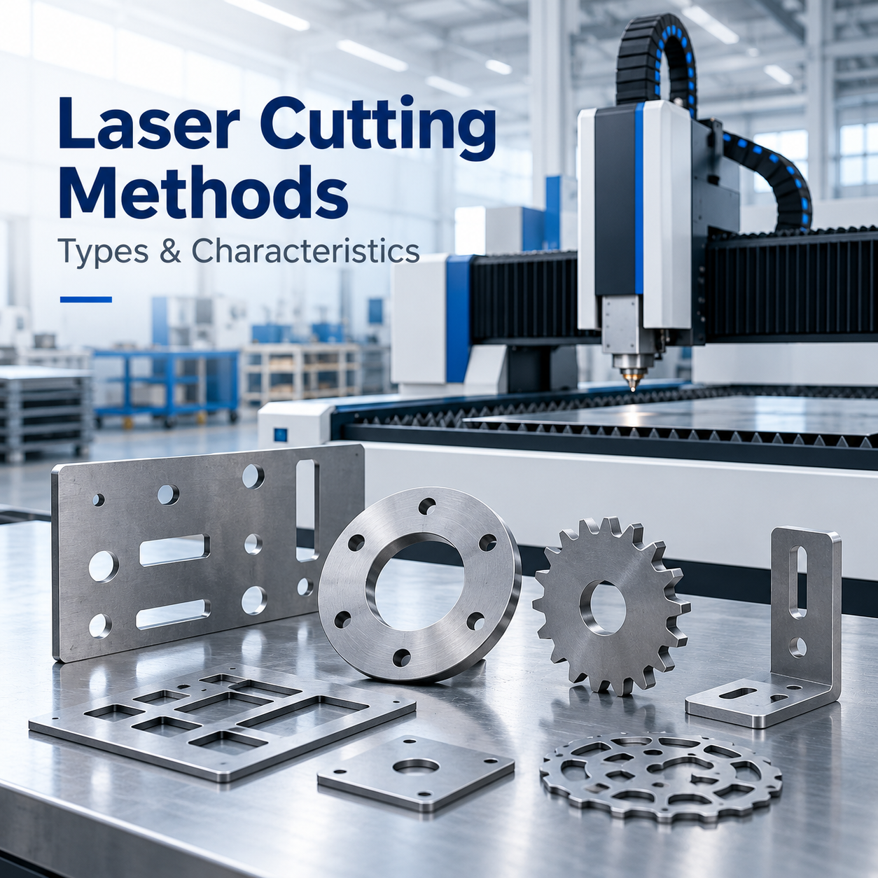
A laser-cut edge can look simple on a drawing. In production, the result depends on what happens in the kerf: does the material vaporize, melt, react with oxygen, or crack in a controlled way? Choosing the wrong process can mean excess heat, rough edges, or avoidable finishing work.
At HDT, our listed fiber laser cutting service covers metal thicknesses from 0.5 to 30 mm, with a 6,000 W fiber laser. Those figures describe a listed capability, not a promise that every alloy, contour, or tolerance will run the same way. The material and the required edge still decide the process.
Use this guide to match the cutting mechanism to the material, understand what the edge tells you, and prepare a drawing that is useful for quoting and production.
Contents
· How the laser creates a cut
· Four laser cutting mechanisms
· What changes the edge and production result
· A practical comparison of methods
· Case study: coil-fed cutting at Fendt
· Questions to settle before a quote
· Frequently Asked Questions
· A practical next step
How the laser creates a cut
A laser cutting machine concentrates light into a small working spot. The focused beam raises the material temperature quickly, while assist gas clears molten material or supports a chemical reaction. The narrow path left by the beam is the kerf. Its width and quality depend on more than laser power: focus position, nozzle condition, gas type and pressure, feed rate, material grade, thickness, and part geometry all matter.
That is why a power rating alone is a poor way to compare quotes. A 6 kW system does not guarantee the same edge on every 6 mm sheet. If the part needs a clean visible edge, tight corner detail, or a particular finish after cutting, those requirements belong in the RFQ, not in a note added after the first sample.
Four laser cutting mechanisms
The four mechanisms in the original technical material are useful because they explain why laser cutting is not one uniform operation. A machine may use different process settings and assist gases depending on whether heat, melt removal, oxidation, or controlled fracture does the main work.
Laser vaporization cutting
A concentrated beam heats the material until it vaporizes. The vapor escapes and leaves a narrow cut. Because vaporization takes substantial energy, the process is most useful for thin sections and selected non-metal materials such as paper, wood, plastics, and textiles. For metals, it is generally not the default choice for thick plate. Material composition and laser wavelength also affect whether it is suitable.
Laser fusion or melt cutting
Here, the beam melts the material, and a coaxial stream of non-reactive assist gas pushes the liquid out of the kerf. Nitrogen is commonly used for stainless steel and other applications where an oxide layer is undesirable; argon may be selected for particular reactive alloys or process requirements. Gas purity and pressure influence the cut, so they should be treated as process inputs rather than minor consumables.
Laser oxygen cutting
Oxygen reacts with the hot metal and adds heat to the process. This can support efficient cutting of readily oxidized materials such as carbon steel, but the resulting edge may carry oxide and can need cleaning or further processing depending on the application. If the edge will be welded, coated, or used as a visible surface, agree the acceptable condition before production.
Laser scribing and controlled fracture
Brittle materials may be scored with a shallow laser line and then separated using controlled force or thermal stress. The beam creates a defined path; it does not simply melt through the full thickness. This approach is used for selected glass and ceramic applications, but material flaws, thickness variation, and the desired edge quality can change the result. It should not be confused with ordinary sheet-metal profile cutting.
What changes the edge and production result
The material name is only the starting point. Two sheets labeled “stainless steel” can behave differently because of grade, surface condition, coating, and thickness tolerance. Reflectivity and thermal conductivity affect how energy couples into the workpiece. A protective film can also leave residue or interfere with processing if it is not specified and tested.
For a metal part, define the edge outcome in practical terms: acceptable dross, burr direction, oxide condition, perpendicularity, and whether secondary deburring is allowed. On thin sheet, a small change in focus or speed can affect heat input and distortion. On thick plate, gas delivery and removal of melt become more important. Fine details and small holes may need different limits from long straight cuts.
A useful drawing package should include the material grade, nominal thickness, coating or film, critical dimensions, quantity, and finish requirements. Mark only the dimensions that truly matter. If the part will be bent or welded later, include those downstream operations; a cut that is dimensionally acceptable before forming may not leave enough allowance for the finished assembly.
A practical comparison of methods
This table is a starting point for a process discussion, not a substitute for a test cut. Laser output depends on the material, equipment configuration, gas, and edge specification.
Method | What does most of the work | Often considered for | Buyer should check |
Vaporization | Material is heated until it becomes vapor | Thin sections and selected non-metals | Thickness, material response, fumes and edge requirement |
Melt cutting | Assist gas ejects molten material | Stainless steel, aluminum and other suitable metals | Gas type and purity, dross, oxide limits and cut quality |
Oxygen cutting | Oxidation adds heat while gas clears the kerf | Carbon steel and other readily oxidized metals | Oxide layer, downstream welding or coating, edge cleanup |
Scribing / controlled fracture | A score line guides a later split | Selected brittle materials such as glass or ceramics | Crack path, material consistency, break force and edge finish |
Case study: coil-fed cutting at Fendt
A published TRUMPF case involving Fendt shows how the cutting setup can affect material use as well as the cut itself. Fendt was producing tractor cab and hood panels. As demand grew, the team wanted more output without expanding the available production area. It moved from sheet loading to laser blanking directly from coil, with part layouts nested along a continuous strip.
In its reported calculations, Fendt estimated about 20% less material for the same result, around 600 work hours freed per year from pallet changes, and roughly 14% more total production time from the laser system. These are results from one plant, product mix, and coil-fed line; they are not a general savings guarantee for standard flat-sheet cutting. The transferable lesson is narrower: nesting, handling, and loading can be as important as the beam when a buyer is looking at cost per accepted part.
For a job shop or a custom order, coil-fed production may not fit the geometry or order size. Still, the case is a good reminder to ask where cost is actually accumulating: material yield, machine time, loading, sorting, or finishing.
Questions to settle before a quote
A clear RFQ lets an engineering team judge whether the requested process fits the part. Include the latest drawing revision and state which features are critical. If you are comparing suppliers, use the same material grade, thickness, tolerance, annual quantity, and finish requirement for each quote.
· Material grade, thickness, coating, and any protective film
· CAD file and drawing revision, including critical tolerances
· Required edge condition and any deburring or surface treatment
· Part quantity, repeat-order outlook, and delivery destination
· Whether cutting is followed by bending, welding, coating, or assembly
HDT lists fiber laser cutting for 0.5–30 mm metal and a 6,000 W system. A project near the edge of that listed range still needs a feasibility check against the actual alloy, geometry, and acceptance criteria. A sample cut or first-article review is the sensible step when edge condition or downstream fit is critical.
Frequently Asked Questions
Which laser cutting method is best for stainless steel?
Melt cutting with a suitable non-reactive assist gas is commonly selected when an oxide-free or clean edge is important. The final choice depends on grade, thickness, tolerance, gas specification, and whether the edge will be finished or welded.
Can one laser cutting machine process both metal and non-metal materials?
Some laser platforms are designed for different material groups, but a metal fiber laser service should not be assumed to process every non-metal. Wavelength, machine configuration, extraction, fire controls, and material safety all matter. Confirm the specific machine and material before sending a job.
Why does a laser-cut edge have dross or burrs?
Dross can result from an unsuitable combination of focus, speed, gas flow, nozzle condition, or material. A drawing should define the allowed edge condition and whether secondary deburring is acceptable; “laser cut” alone does not define a finished-edge standard.
Does a higher laser power always mean a better cut?
No. Power is one process variable. Focus, beam quality, motion control, gas delivery, material condition, and the target edge all affect the result. Compare parts against the same acceptance criteria rather than comparing wattage alone.
A practical next step
Laser cutting works best when the process is chosen around the material and the finished part, not a power number in isolation. Share your drawing, grade, thickness, and edge requirements with HDT, and our team can review the fit and prepare a project-specific quote.